Raw material geometry affects every stage of the machining process. Setup time, cutting tool selection, material waste, and finished component accuracy all shift depending on whether starting stock is flat or round. Tool Steel Flat Bar and Tool Steel Round Bar each carry machining advantages that make them the right choice for different component geometries. Understanding those advantages before placing a stock order separates efficient machining operations from those that lose time and material on the wrong starting form.
Understanding Tool Steel Flat Bars and Round Bars
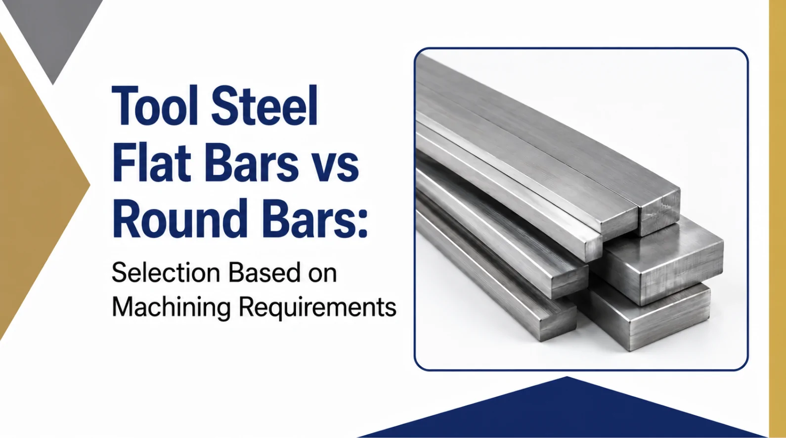
Tool Steel Flat Bars
Tool steel flat bars have a rectangular cross-section that suits components needing flat, planar surfaces. They come in multiple flat bar sizes and are the standard starting stock for dies, fixtures, plates, and structural tooling components. The geometry does significant material removal work before machining even begins.
Tool Steel Round Bars
Tool steel round bars have a cylindrical cross-section for components that rotate or need concentric geometry. Shafts, rollers, pins, and bushings start from round bar stock because the circular geometry aligns with the finished component shape. Both forms are available in multiple tool steel grades, with flat bar sizes and diameters chosen to minimize machining allowance.
Machining Advantages of Tool Steel Flat Bars
Flat bar steel carries its machining advantage in the geometry. A rectangular starting cross-section requires less material removal than turning a round bar to a flat component shorter cycle times, lower cutting tool wear, and less machining scrap follow directly. Flat surfaces also clamp securely in vises and fixtures without the rotational tendency that round bar creates during milling. Better dimensional stability and more consistent surface finishes are the result. For dies, cutting tools, machine bases, and support plates, Tool Steel Flat Bar is the efficient starting choice the stock geometry aligns with the component geometry.
Machining Advantages of Tool Steel Round Bars
Rotational components are where Tool Steel Round Bar earns its place. CNC turning works directly with the bar’s cylindrical geometry; the lathe centers on the bar’s axis and removes material concentrically to produce shafts, pins, rollers, and bushings with high dimensional accuracy. Uniform stress distribution around the circular cross-section reduces edge stress concentration, important for components carrying torsional loads. Lathe machining of round bar is faster than producing cylindrical components from flat stock because starting geometry eliminates preliminary milling operations.
Material Utilization and Machining Waste Comparison
Starting stock shape determines machining waste directly. Cutting a rectangular die insert from flat bar leaves minimal offcuts; cutting the same part from round bar wastes the corner material on every piece. The reverse applies for cylindrical components, turning a shaft from round bar wastes only the machining allowance, while milling from flat bar wastes corner stock on all four sides. Flat bar weight calculations for rectangular components show better material yield than round bar for the same finished geometry. Selecting incorrect stock shapes inflates both material spend and processing time on every production run.
Strength and Structural Considerations
Flat Bars
Tool steel flat bars carry compressive and bending loads efficiently across their wide flat surface suited for structural supports, die bases, and tooling plates that face downward or lateral loading.
Round Bars
Round bars provide superior torsional strength. The circular cross-section distributes torsional stress uniformly, making the round bar correct for rotating shafts, drive components, and high-stress cylindrical fasteners. MS flat bar in structural and general fabrication applications benefits from efficient planar load distribution geometry selection should always match the load direction the finished component carries in service.
Tool Steel Flat Bars vs Round Bars: Quick Comparison Table
Compare the essential differences between flat and round tool steel bars to optimize your machining workflow:
| Feature | Tool Steel Flat Bar | Tool Steel Round Bar |
| Shape | Rectangular | Cylindrical |
| Best Machining Process | Milling and Surface Grinding | Turning and CNC Lathe |
| Material Utilization | High for flat components | High for round components |
| Workholding Stability | Excellent | Moderate |
| Rotational Applications | Limited | Excellent |
| Common Applications | Dies, Fixtures, Plates | Shafts, Pins, Rollers |
| Machining Waste | Lower for flat parts | Lower for round parts |
How to Select the Right Bar Shape for Machining
Component geometry is the primary selection driver. Flat bar is the raw material for mostly flat finished products, like die plates, mold inserts, and support fixtures. Most finished items are cylindrical in shape, such as shafts, rollers and precision pins, starting with a round bar. Using stock symmetry to match the geometry of the components reduces machining time and material waste. Uniform dimensional tolerances and material properties throughout the whole production runs are provided by precision-grade materials from reputable vendors. At IMI Alloys India we manufacture quality tool steel flat bars and round bars of various grades and sizes.
Conclusion
Both tool steel flat and round bars deliver genuine machining advantages when you match them to the correct job. Flat bars optimize structural and machined parts because their rectangular shape slashes your setup times and raw material waste. Round bars maximize turned and rotational parts because working with circular geometry unlocks highly accurate, fast, and repeatable lathe operations on your shop floor. First, assess your component geometry, machining process and material utilization needs. IMETAL India’s tool steel flat bar and tool steel round bar products are stocked to ensure they are consistent and precision grade, and function reliably during every stage of your machining operation.